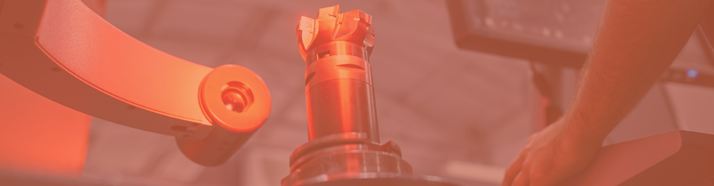
Outer diameter measurement

Complying with outer diameter specifications for parts such as tubes, shafts or axles is a challenge for their manufacturers. Pneumatic, tactile or optical methods can address these needs.

SHAFT AXIS

    Keep in touch

    Receive SETSMART exclusive content including market insight, special offers, industrial developments…

    You can unsubscribe at any time

    This website is protected by reCAPTCHA, and Google’s privacy policy and terms of use apply.

    Why controlling outside diameters?

    Measuring the outer diameter of tubes, shafts and other pins is an important step in their manufacturing process. For quality control purposes, measuring the outer diameter ensures that the product meets the specified dimensions and tolerances. This maintains the quality of the product and of its manufacturing process.
     
    The outside diameter of a shaft or tube must be suitable for the other components with which it will be assembled, such as bearings, gears or other tubes. Checking this outside diameter after manufacturing ensures that the parts, once assembled, will have the desired level of clearance or interference.
     
    While very simple tools such as calipers or outside micrometers exist, they do not offer the accuracy, level of traceability or automation that are required by the industry.

    Controlling the diameters of tubes, shafts or axles by the pneumatic method

    Pneumatic measurement is widely used to check the external dimensions of manufactured parts. In the specific case of tube and shaft diameters, the air ring technology is used.
     
    This sensor consists of a hollow ring in which a flow of compressed air circulates, with at least two small outlet orifices directed towards the inside of the ring. It is inserted around the cylindrical part to be measured.


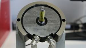
    The pressure of the air flow varies according to the spacing between the orifices and the edges of the controlled part. The measured diameter is materialized by a height of liquid which depends on this pressure, or by its graphical display on a software. This height of liquid is compared to the one obtained for standard parts of the desired diameters.


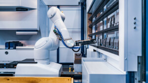
    Ouside diameters control using touch probes

    Touch probe technology is widely used to measure external dimensions of parts, especially diameters. The sensor technologies used include digital, linear displacement (LVDT), touch-triggered, or scanning probes.
    These sensors are usually attached to a machine by means of robots that can move them while always knowing their position in space.
     
    They are set in motion until a contact with the surface of the part to be checked is detected. The coordinates of the contact point(s) are then recorded. These coordinates are compared to calculate the outer diameter to be checked. Depending on the technology used, the probes measure either two fixed points or a series of points around the circumference of the part.
     

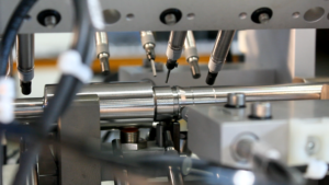
    The technique is quite universal and allows, depending on the sensors and robots chosen, to design machines specialized in the control of certain families of parts or very versatile machines capable of controlling a large number of different parts. The touch probe technology principle does not allow the inspection of parts whose surface could be damaged by contact with the probe.


    Ouside diameters control using industrial vision

    Optical micrometers are often used to check outer diameters because they are a fast and accurate way to measure the dimensions of cylindrical objects such as tubes, shafts or axles. They use a non-contact measurement method that reduces the risk of damage or wear to the object being measured.
     
    Optical micrometers work by placing the object to be checked between a light beam and an optical receiver. The shadow formed by the object is reconstructed on a digital image. An image processing algorithm determines the height of the shadow, and translates it into the diameter of the object.
     

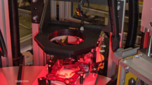
    In addition to their accuracy and non-contact measurement method, optical micrometers are also easy to use and can measure a wide range of object sizes and shapes. The high measurement rate of optical micrometers and the fast processing speed of the software allow this method to be used in-line, directly on the manufacturing process.


    Manual, automated, analog or digital control?

    The pneumatic method, generally manual, can integrate automation and robots to handle the parts, move the measuring rings, and even sort the parts according to their conformity. These systems can be adapted to the measurement rates required by the user.
    The results of outer diameter measurements, regardless of the method used, can be recorded using software. The software offers several useful functions, such as programming of inspection procedures, display of simple diameter measurement results for quick decision making, statistical calculations of result series and automated generation of inspection reports.
    In addition, measurement data logging and management of administrator or user accounts provide a traceability level that analog systems cannot match. In the case of probe measurement, the software can generate a digital image from the measured coordinates. As with optical measurements, the image can then be analyzed using an algorithm or image processing function to determine the desired diameters.

    ASSOCIATED SETSMART TECHNOLOGIES

    Visit the technology pages for more information on the control techniques used