Inspection of micrometric orifices
Many manufactured parts have orifices that perform their primary function. Checking the diameter, shape and non-obstruction of these apertures will ensure that the part will perform its primary function correctly.
The challenges of inspecting orifices
The internal dimensions of small apertures are more difficult to measure, and therefore to control, than larger bores or holes. While dimensional measurement tools such as calipers or bore gauges exist, these techniques are simply not applicable for holes that are one millimeter in diameter or smaller.
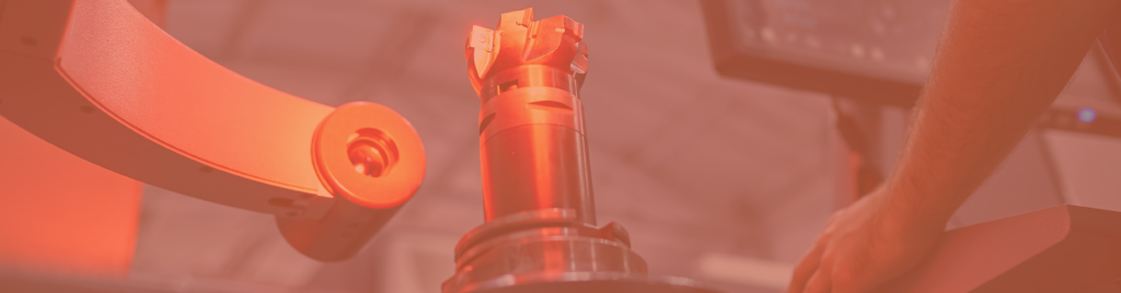
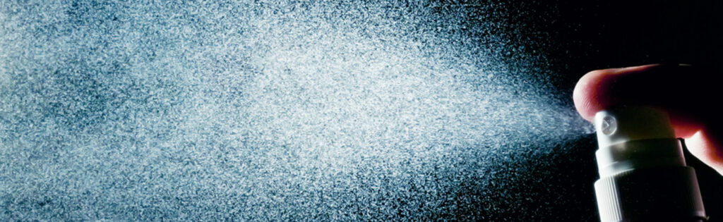
But these holes, their diameters and shapes, can be critical to the part that bears them. This is the case, for example, for industrial spray nozzles, spray actuators for the cosmetics or pharmaceutical industries, ventilation channels for parts operating at high temperatures, etc.
If the company in charge of the mass production of this kind of parts is able to ensure their geometrical parameters, it will at the same time guarantee its customer the quality of the supplied products.
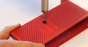
Inspection of orifices by the pneumatic method
Pneumatic measurement is a method based on the analysis of the pressure change resulting from the variation of an air flow through an orifice.
The device making this measurement possible is called a pneumatic flowmeter, a measuring column, or a pneumatic comparator. It is mainly composed of :
- A system for regulating the pressure of the air flowing inside the device.
- An outlet of this air flow: it is directed towards the orifice to be controlled with the help of an adaptor. The outlet pressure of the air flow depends on the size and shape of the orifice.
- A system for detecting the difference between the internal pressure and the outlet pressure. The detection system is typically a column of liquid whose height depends on the pressure difference, or its graphic representation on software.
The method consists first of all in measuring this pressure difference on one or more standard orifices considered good or bad: target value, minimum tolerance, maximum tolerance. The corresponding liquid heights are marked.
Then the series of parts to be controlled is measured, and the values of the pressure differences are compared to the measured target and limit values.
In addition to non-compliance with specified orifice diameters and shapes, the method also allows the detection of obstructions, since these obstructions cause a pressure increase because the air can’t flow through the orifice.
Analog or digital control?
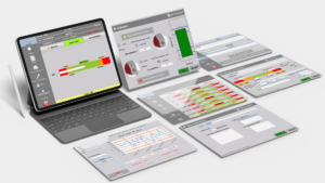
As mentioned above, some devices convert the dimension of the orifice into a digital value displayed on a graph.
The software allowing this representation also has very interesting functions for the user: programming of control procedures of various types of orifices, display of simple measurement results for quick decision-making, statistical calculations on series of results, automatic generation of measurement reports.
Thanks to the recording of measurement data and the management of administrator or user accounts, they also offer a level of results traceability for the control of micrometric orifices that is not possible with analog systems.
ASSOCIATED SETSMART TECHNOLOGIES
Visit the technology pages for more information on the control techniques used